Mechanical Design Symbols Charts and Abbreviations
Classification:BLOG
I. Introduction
Write an introduction to a blog article
Mechanical design is a critical field that involves creating and designing products and systems that use mechanical principles and elements. From automobiles and aircraft to manufacturing machinery and medical devices, mechanical design plays a vital role in the development and operation of a wide range of products and systems.
One important aspect of mechanical design is the use of standard symbols and abbreviations to convey information clearly and accurately. These symbols and abbreviations are used on drawings, schematics, and other technical documents to represent various components, materials, dimensions, and other important details. By using these standardized symbols and abbreviations, engineers and other professionals can easily and quickly understand and interpret the information being conveyed.
In this article, we will provide an overview of common symbols and abbreviations used in mechanical design. We will cover symbols for geometric shapes, dimensions and tolerances, materials and finishes, fasteners and connectors, mechanical components, and electrical components. Understanding these symbols and abbreviations is essential for anyone working in mechanical design or related fields.
Common Engineering Drawing Abbreviations
The technical engineering drawing abbreviations we outline here are the terms used in the manufacturing and inspection of parts and assemblies. You can find the list of common engineering drawing abbreviations.
|
AF: Across Flats |
LH: Left hand |
I/D: Internal diameter |
|
ASSY: Assembly |
LG: Long |
JT: Joint |
|
CM: Centimeters |
M/C: Machine |
KG: Kilogram |
|
CL: Center line |
MATL: Material |
BC or B.C.: Bolt circle |
|
CHAM: Chamfered |
MAX: Maximum |
BHC: Bolt hole circle |
|
CH HD: Cheese Head |
M: Meter |
BRZ: Bronze |
|
CSK: Countersink |
MM: Millimeter |
CAD: Computer-aided design |
|
CSK HD: Countersink Head |
MIN: Minimum, Minute |
CERT: Certification |
|
C’BORE or CBORE: Counterbore |
NTS: Not to scale |
CI: Cast iron |
|
CYL: Cylinder or Cylindrical |
NO.: Number |
CNC: Computer Numerical Control |
|
DATUM: Datum System |
O/D: Outside diameter |
CRES: Corrosion-resistant |
|
“: Degree (of angle) |
PCD: Pitch circle diameter |
DIM: Dimension |
|
DIA: Diameter |
QTY: Quantity |
ED: Edge distance |
|
DIM: Dimension |
LB: Pound |
IAW: In accordance with |
|
DRG: Drawing |
RAD or R: Radius |
LMC: Least material condition |
|
ENG: Engine, engineering |
RPM: Revolutions per minute |
MBP: Measurement between pins |
|
EQUI SP: Equally Spaced |
RH: Right hand |
MBW: Measurement between wires |
|
EXT: External |
RD HD: Round head |
MFD: Manufactured |
|
FIG: Figure |
SCR: Screwed |
MFG: Manufacturing |
|
FT: Foot |
SK: Sketch |
MFR: Manufacturer |
|
GAL: Gallon |
SPEC: Specification |
MMC: Maximum material condition |
|
GALV: Galvanized |
SPH: Spherical |
OAL: Overall length |
|
HRA: Hardness Rockwell A scale |
SQ: Square |
PC: Piece |
|
HRB: Hardness Rockwell B scale |
STD: Standard |
PD: Pitch diameter |
|
HRC: Hardness Rockwell C scale |
SWG: Standard wire gauge |
PL: Parts list |
|
HRD: Hardness Rockwell D scale |
THD: Thread |
PMI: Product and manufacturing information |
|
HRE: Hardness Rockwell E scale |
TPI: Thread per inch |
REF: Reference |
|
HB: Hardness Brinell |
VOL: Volume |
RZ: Roughness, mean depth |
|
HV: Hardness Vickers |
WT: Weight |
SFACE: Spotface |
|
HEX: Hexagon |
AC: Across corners |
SN: Serial number |
|
HEX HD: Hexagon head |
ALY: Aluminum |
STD: Standard |
|
HYD: Hydraulic |
ANN: Anneal |
UNC: Unified National Coarse |
|
IN: Inch |
AQL: Acceptable quality level |
UNS: Unified National Special |
|
INSUL: Insulated, insulation |
AR: As required |
YS: Yield Strength |
|
INT: Internal |
AVG: Average |
|
|
BASIC or BSC: Basic dimension |
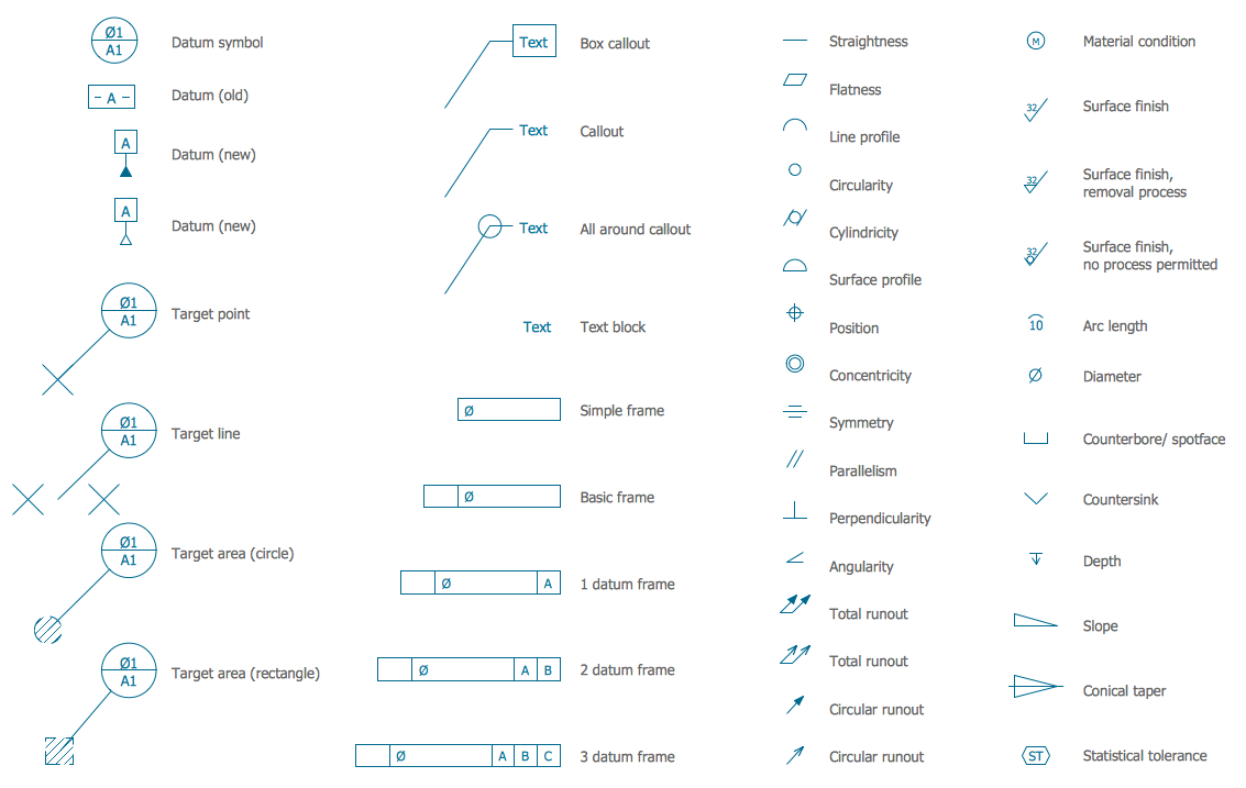
Engineering Drawing Symbols
Basic types of symbols used in engineering drawings are countersink, counterbore, spotface, depth, radius, and diameter. Here are more commonly used engineering drawing symbols and design elements as below. You can also check out the GD&T symbols and termson our site.
II. Symbols for Geometric Shapes
Symbols for geometric shapes are an essential part of mechanical design and are used to represent various shapes and lines on drawings and schematics. These symbols are used to convey information about the size, orientation, and other characteristics of the shapes being depicted.
Lines: There are various types of lines used in mechanical design, including straight lines, curved lines, and dashed lines. Straight lines are used to represent straight edges or surfaces, while curved lines are used to represent curved edges or surfaces. Dashed lines are often used to indicate hidden lines, center lines, or cut lines.
Circles and arcs: Circles and arcs are used to represent circular shapes and arcs. They are often used to indicate holes, openings, or other circular features.
Polygons: Polygons are geometric shapes with multiple sides, such as squares, triangles, and hexagons. These shapes are often used to represent flat surfaces or edges.
By using these symbols to represent geometric shapes, engineers and other professionals can clearly and accurately convey information about the shapes and lines present in a given design. It is important to carefully review the symbols and abbreviations being used to ensure that you understand the information being conveyed.
III. Symbols for Dimensions and Tolerances
Accurate dimensions and tolerances are critical in mechanical design, as they ensure that a product or system will function as intended. In order to convey this information clearly and accurately, specific symbols are used to represent dimensions and tolerances on drawings and schematics.
Lines and arrows indicating dimensions: Lines and arrows are used to indicate the size or length of a particular feature or component. These lines and arrows are typically accompanied by numerical values that specify the exact size or length being depicted.
Tolerance symbols: Tolerances specify the acceptable range of variation for a particular dimension or feature. There are several symbols used to indicate tolerances, including plus/minus symbols and limits symbols. Plus/minus symbols indicate that the specified dimension can vary by a certain amount in either direction, while limits symbols indicate the maximum and minimum acceptable dimensions for a particular feature.
By using these symbols to represent dimensions and tolerances, engineers and other professionals can clearly and accurately convey the precise size and acceptable range of variation for a given component or feature. It is important to carefully review the symbols and abbreviations being used to ensure that you understand the information being conveyed.
IV. Symbols for Materials and Finishes
The choice of materials and finishes for a product or system can have a significant impact on its performance and appearance. In order to convey this information clearly and accurately, specific symbols are used to represent materials and finishes on drawings and schematics.
Materials: There are a wide variety of materials used in mechanical design, including steel, aluminum, plastic, and many others. These materials are often represented by specific symbols or abbreviations on drawings and schematics. For example, steel is often represented by the letter "S," while aluminum is represented by the letter "A."
Finishes: The finish of a particular component or feature can also be important in mechanical design. Finishes such as rough, smooth, and painted are often represented by specific symbols or abbreviations on drawings and schematics. For example, a rough finish may be represented by a series of short, closely spaced lines, while a smooth finish may be represented by a single long line.
By using these symbols to represent materials and finishes, engineers and other professionals can clearly and accurately convey the specific materials and finishes being used in a given design. It is important to carefully review the symbols and abbreviations being used to ensure that you understand the information being conveyed.
V. Symbols for Fasteners and Connectors
Fasteners and connectors are essential components in many mechanical systems, as they are used to secure and connect various parts and components together. In order to convey information about these components clearly and accurately, specific symbols are used on drawings and schematics.
Screws, bolts, nuts, and washers: These common fasteners are often represented by specific symbols on drawings and schematics. For example, a bolt may be represented by a circle with a cross inside, while a nut may be represented by a square with a diagonal line. The size and type of fastener being used may also be indicated by specific symbols or abbreviations.
Weld symbols: Weld symbols are used to indicate the type and location of a weld on a drawing or schematic. These symbols typically include a reference line, arrow, and other symbols or abbreviations that specify the type of weld, size, and other details.
Connectors: Pins, clips, and other connectors are often represented by specific symbols on drawings and schematics. These symbols may include circles, squares, or other shapes to indicate the type of connector being used.
By using these symbols to represent fasteners and connectors, engineers and other professionals can clearly and accurately convey the specific components being used in a given design. It is important to carefully review the symbols and abbreviations being used to ensure that you understand the information being conveyed.
VI. Symbols for Mechanical Components
Mechanical components are essential elements in many mechanical systems, and the specific components used can have a significant impact on the performance and function of the system. In order to convey information about these components clearly and accurately, specific symbols are used on drawings and schematics.
Gears, springs, bearings, and other mechanical components: These components are often represented by specific symbols on drawings and schematics. For example, a gear may be represented by a circle with teeth around the perimeter, while a spring may be represented by a series of closely spaced coils. The size and type of component being used may also be indicated by specific symbols or abbreviations.
Hydraulic and pneumatic symbols: Hydraulic and pneumatic systems are used in many mechanical systems to transmit and control fluid power. Specific symbols are used to represent various components and elements of these systems on drawings and schematics. For example, a pump may be represented by a circle with a triangle inside, while a valve may be represented by a square with a diagonal line.
By using these symbols to represent mechanical components, engineers and other professionals can clearly and accurately convey the specific components being used in a given design. It is important to carefully review the symbols and abbreviations being used to ensure that you understand the information being conveyed.
VII. Symbols for Electrical Components
Electrical components are an essential part of many mechanical systems and products, and the specific components used can have a significant impact on the performance and function of the system. In order to convey information about these components clearly and accurately, specific symbols are used on wiring diagrams and schematics.
Wiring and schematics: Wiring diagrams and schematics are used to represent the electrical connections and circuits within a system. These diagrams and schematics use specific symbols to represent various components, such as wires, switches, and other electrical components. The specific symbols used can vary depending on the type of component and the standards being followed.
Switches, transformers, motors, and other electrical components: These components are often represented by specific symbols on wiring diagrams and schematics. For example, a switch may be represented by a triangle with a single line or a double line, while a transformer may be represented by two interconnected circles with lines or dots on one side and dots on the other side. The size and type of component being used may also be indicated by specific symbols or abbreviations.
By using these symbols to represent electrical components, engineers and other professionals can clearly and accurately convey the specific components being used in a given system or design. It is important to carefully review the symbols and abbreviations being used to ensure that you understand the information being conveyed.
VIII. Conclusion
Mechanical design relies on the use of standard symbols and abbreviations to convey information clearly and accurately. These symbols and abbreviations are used on drawings, schematics, and other technical documents to represent various components, materials, dimensions, and other important details. By using these standardized symbols and abbreviations, engineers and other professionals can easily and quickly understand and interpret the information being conveyed.
It is essential to carefully review the symbols and abbreviations being used in a given project to ensure that you fully understand the information being conveyed. Not only is this important for the success of the project itself, but it is also important for safety and compliance with industry standards.
In summary, the use of standard symbols and abbreviations is critical in mechanical design, and it is important to understand the specific symbols and abbreviations being used in a given project. By reviewing and understanding these symbols and abbreviations, you can effectively communicate and collaborate with other professionals, ensuring the success of your project.
Our most popular products